Bare Metal Programming the STM32
Programming an ARM Cortex M4 without any framework or IDE - just some datasheets and gcc My microcontrollers class in my undergraduate degree used the STM32L476-DISCOVERY for everything. It's a development board with an ARM Cortex-M and a bunch of peripherals. I loved that thing. I've written UART and LCD drivers by interacting with raw registers, set up peripherals using just assembly, controlled a robot over Bluetooth, you name it. But now it's just sitting around, collecting dust. When I wrote code for class, I only ever used the pre-installed, pre-configured Keil IDE the lab had set up. That changes with this project. I want to program this thing with nothing more than a datasheet and gcc. I had attempted this once before unsuccessfully, but since then I have found this remarkable resource by cpq. It details fairly closely what I wanted to do. It helped fill in gaps in my knowledge about the process, but I still had to look up and find lots of details in my datasheets since I was using a different (and much older) processor than in the tutorial. First thing's first, let's get some software. I needed The procedure for bare-metal ARM programming is this: Important points: The trickiest part for the uninitiated is probably going to be writing the linker script. If you can, use a premade one (like the one below) and modify it. So after defining a main.c: link.ld: And the build command: And then making the binary to be flashed: And then the flash command: And success! I wonder if making the output format of In fact, let's go one step further and look at it closely: firmware.bin: Yeah, that looks exactly like what I would expect. The initial stack pointer in little endian, followed by the pointer to Let's adapt the Makefile from the bare metal programming tutorial to match our project directory. Okay, let's set up the GPIO registers as shown in the "STM32L47xxx, STM32L48xxx, STM32L49xxx and STM32L4Axxx" reference manual. GPIO pins are grouped by ports. My current understanding is it's simply a means of grouping pins togeher, although I'm sure there is more to it. You'll have to look at the documentation on how to enable GPIO pins. It's pretty typical to have to do the following: Trouble with getting anything to work? Have you plugged in a debugger and seen your write commands to peripheral registers have no effect whatsoever? You probably don't have the right clock set up. Make sure: These steps are especially important for devices meant for low power, cause they tend not to start them by default to save juice. CHECK THE GIVEN OFFSETS! Just because one register comes right after another in a datasheet, you cannot assume they are contiguous. First, Check if your spin function is taking too long. Turns out I grossly underestimated how long each one of those cycles would take. This code has been working for much longer than I gave it credit for. Second, take a break. Come back and look at it tomorrow. Fresh eyes see a lot. Sincerely, Most of my Saturday I truly believe documentation is one of the biggest factors in the success of a project. If it's easy to find out answers to your questions and to browse through available material so you pick up new knowledge and tricks, you're golden. Too often, though, and especially with embedded devices, the documentation you need is just not to be found, or worse: is available, but hasn't been provided to you. This is my best guess for what to look for. Note that what you're not usually looking for are things that apply to all Cortex-M processors or Cortex-M4s or M33s or whathaveyou. Those docs from ARM are more focused on the architecture of their family of Cortex processors: pipelines, assembly instructions, that sort of thing. Remember that ARM provides the computation core designs and silicon manufacturers actually design, layout, fab, and document the chips you're using. This includes all the peripherals, like GPIO, I2C, and ADCs. Most of the time as an embedded dev you'll be dealing with peripherals, the manufacturer-specific parts. However, sometimes you do need to reference something that is common to all Cortex-Ms or something like that. The first thing I would do is look for what architecture your chip uses. For example, Cortex-M4s use the ARMv7-M architecture, so I look for the ARMv7-M Architecture Reference manual to find documentation on things like SysTick. Honestly, though, if you want to learn what's common between different processor families or groups ("Is this feature on all Cortex-M0s?"), Wikipedia will be a faster resource for learning than combing datasheets. So that's your task. When you're trying to program something, try to get those three or so documents: In the end, I was able to tune the wait function well enough to get some blinking action going! Behold, in all its glory, the entirely manually-programmed blinkenlight: Background
Downloading Requisite Software
The Procedure
#define-ing their pointers and making a nice C interface into them. Execution
_reset handler, writing a linker script to put the interrupt vector at the beginning of your binary, and filling out a bare-bones main.c, we have this:int main(void);
// Startup code
__attribute__((naked, noreturn))
void _reset(void)
{
// memset .bss to zero, and copy .data section to RAM region.
extern long _sbss, _ebss, _sdata, _edata, _sidata;
// _sbss et al. are symbols that are located at the start of BSS, etc. So if we
// want the address of the start of BSS, we take &_sbss.
for (long *dst = &_sbss; dst < &_ebss; dst++)
{
*dst = 0;
}
for (long *dst = &_sdata, *src = &_sidata; dst < &_edata;)
{
*dst++ = *src++;
}
main(); // Call our pitiful main function.
for (;;) (void) 0; // Infinite loop
}
extern void _estack(void); // Defined in link.ld
// 16 standard and 81 STM32L476-specific handlers
#define NUM_PERIPHERAL_INTERRUPTS (81)
#define NUM_ARM_GENERAL_VECTOR_ENTRIES (16)
// Freakin C function pointer syntax.
// Makes an array of pointers to functions of type void(void)
__attribute__((section(".vectors")))
void (*const vector_table[NUM_ARM_GENERAL_VECTOR_ENTRIES + NUM_PERIPHERAL_INTERRUPTS])(void) = {
_estack,
_reset
// Of course the rest will be zeros by default. This is okay for now.
};
int main(void)
{
return 0;
}ENTRY(_reset);
MEMORY {
flash(rx) : ORIGIN = 0x08000000, LENGTH = 1024k /* 1 Mbyte of flash */
sram(rwx) : ORIGIN = 0x20000000, LENGTH = 96k /* SRAM1 */
/* SRAM2, has hardware parity check, can be retained in standby mode */
/*sram2(rwx): ORIGIN = 0x10000000, LENGTH = 32k */
}
_estack = ORIGIN(sram) + LENGTH(sram); /* Stack points to very end of sram */
SECTIONS {
.vectors : { KEEP(*(.vectors)) } > flash
.text : { *(.text*) } > flash
.rodata : { *(.rodata*) } > flash
.data : {
_sdata = .; /* data section start */
*(.first_data)
*(.data SORT(.data.*))
_edata = .; /* data section end */
} > sram AT > flash
_sidata = LOADADDR(.data);
.bss : {
_sbss = .; /* bss section start */
*(.bss SORT(.bss.*) COMMON)
_ebss = .; /* bss section end */
} > sram
. = ALIGN(8);
_end = .; /* for cmsis_gcc.h */
}
/* I've got a lot to learn about linker scripts, honey. */arm-none-eabi-gcc -T link.ld -nostdlib main.c -o firmware.elfarm-none-eabi-objcopy -O binary firmware.elf firmware.binst-flash --reset write firmware.bin 0x8000000arm-none-eabi-objcopy binary is what made it all work... I was making Intel .hex files before, and they didn't seem to work very well.... I can't remember what source I was following to do that. IIRC ST-Link should be able to handle a variety of formats, but maybe a flat binary image is best. You should be able to just write that to the flash as-is, I would think.00000000: 0080 0120 8401 0008 0000 0000 0000 0000 ... ............
00000010: 0000 0000 0000 0000 0000 0000 0000 0000 ................
00000020: 0000 0000 0000 0000 0000 0000 0000 0000 ................
00000030: 0000 0000 0000 0000 0000 0000 0000 0000 ................
00000040: 0000 0000 0000 0000 0000 0000 0000 0000 ................
00000050: 0000 0000 0000 0000 0000 0000 0000 0000 ................
00000060: 0000 0000 0000 0000 0000 0000 0000 0000 ................
00000070: 0000 0000 0000 0000 0000 0000 0000 0000 ................
00000080: 0000 0000 0000 0000 0000 0000 0000 0000 ................
00000090: 0000 0000 0000 0000 0000 0000 0000 0000 ................
000000a0: 0000 0000 0000 0000 0000 0000 0000 0000 ................
000000b0: 0000 0000 0000 0000 0000 0000 0000 0000 ................
000000c0: 0000 0000 0000 0000 0000 0000 0000 0000 ................
000000d0: 0000 0000 0000 0000 0000 0000 0000 0000 ................
000000e0: 0000 0000 0000 0000 0000 0000 0000 0000 ................
000000f0: 0000 0000 0000 0000 0000 0000 0000 0000 ................
00000100: 0000 0000 0000 0000 0000 0000 0000 0000 ................
00000110: 0000 0000 0000 0000 0000 0000 0000 0000 ................
00000120: 0000 0000 0000 0000 0000 0000 0000 0000 ................
00000130: 0000 0000 0000 0000 0000 0000 0000 0000 ................
00000140: 0000 0000 0000 0000 0000 0000 0000 0000 ................
00000150: 0000 0000 0000 0000 0000 0000 0000 0000 ................
00000160: 0000 0000 0000 0000 0000 0000 0000 0000 ................
00000170: 0000 0000 0000 0000 0000 0000 0000 0000 ................
00000180: 0000 0000 5040 9fe5 0200 00ea 0030 a0e3 ....P@.......0..
00000190: 0030 84e5 0440 84e2 4030 9fe5 0300 54e1 .0...@..@0....T.
000001a0: f9ff ff3a 3840 9fe5 3850 9fe5 0500 00ea ...:8@..8P......
000001b0: 0520 a0e1 0450 82e2 0430 a0e1 0440 83e2 . ...P...0...@..
000001c0: 0020 92e5 0020 83e5 1c30 9fe5 0300 54e1 . ... ...0....T.
000001d0: f6ff ff3a 0500 00eb feff ffea 0000 0020 ...:...........
000001e0: 0000 0020 0000 0020 0c02 0008 0000 0020 ... ... .......
000001f0: 04b0 2de5 00b0 8de2 0030 a0e3 0300 a0e1 ..-......0......
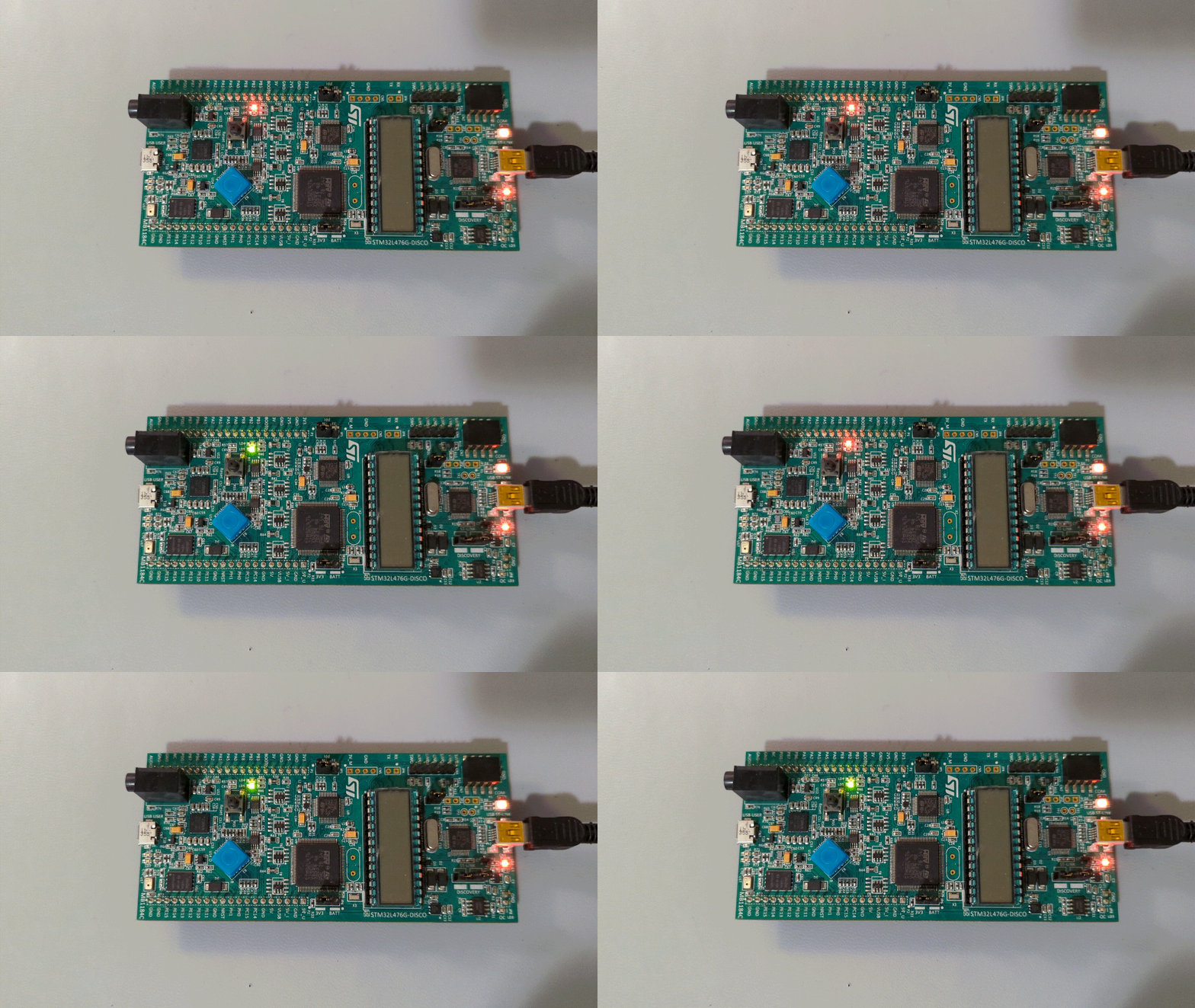
00000200: 00d0 8be2 04b0 9de4 1eff 2fe1 ........../._reset() in little endian, then a whole bunch of 0 pointers, followed by our code at 0x0000 0184, which will be mapped to 0x0800 0184 when this is written to flash. Sweet! Blinking an LED
GPIO Ports
Troubleshooting
Clocking Problems
Memory Offset Errors
I've combed over this code 20 times and I don't see anything wrong
Documentation you'll need for bare metal programming
What you'll need
Less useful resources
Documents Recap
Results