Characterizing a Hall Effect Sensor
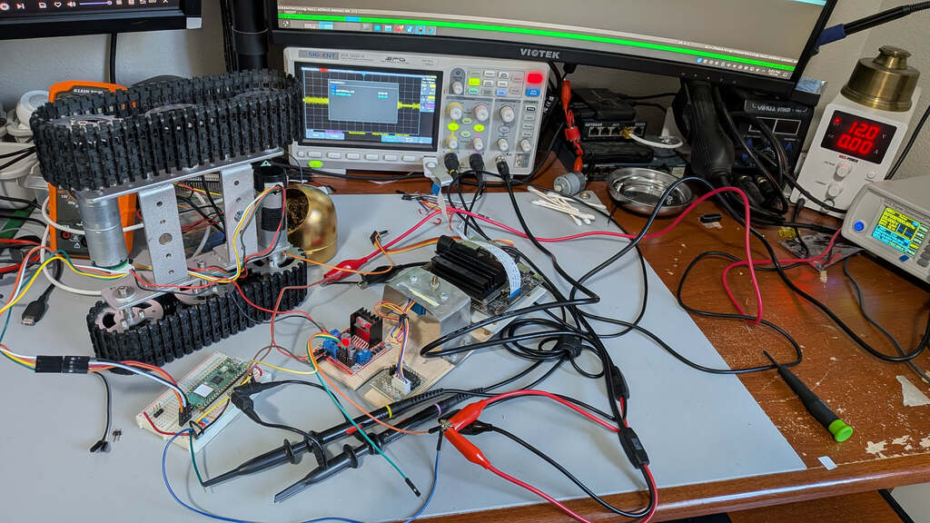
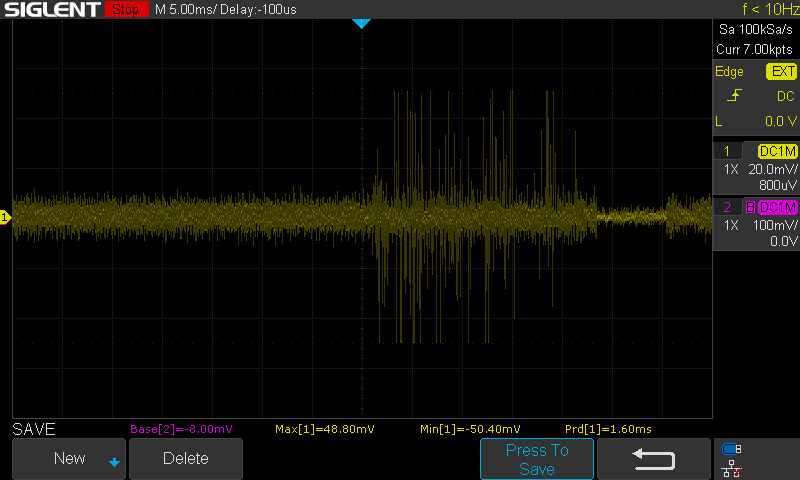
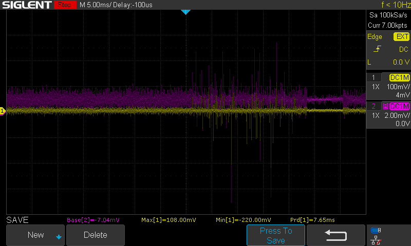
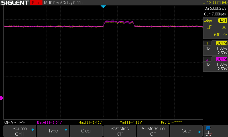
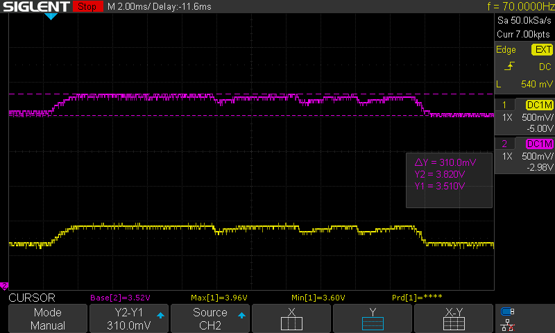
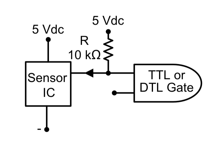
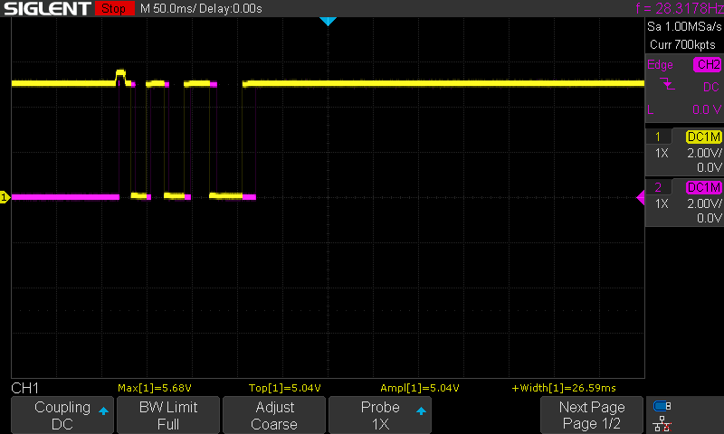
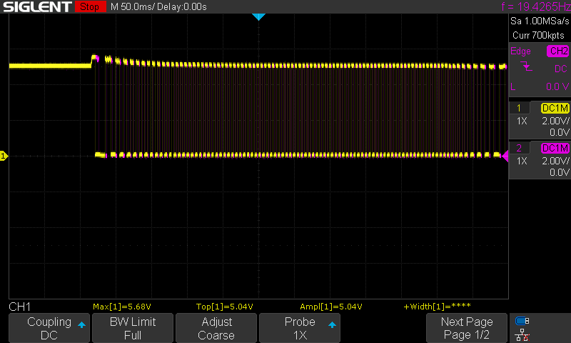
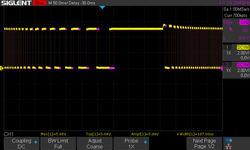
This motor module has a Hall effect sensor hooked up. Let's see what it looks like on a scope! Longtime readers of this blog might recognize this tank tread chassis from multiple robots I've built on it over the years. I think I got it in 2017 or 2018. It has served me well! A couple days ago, as I was revamping my robotics platform, I decided to tackle some maintenance items that had been bugging me for years, but never warranted taking the whole bot apart. First, one of the tank treads has always been noticeably looser than the other. I took out one of the links of the looser one, and they both have similar tautness now. Surprisingly, though, they did have equal numbers of segments (53), but now the modified one has 52 segments. Unequal or not, it now looks a lot smoother! The other thing is that the instructions (now lost to time) had me install one of the motors so the cables coming out of it were pointed into the ground. That has always bugged me as a bad design, so I was able to rotate the motor and install it so both of them have their wires coming up into the payload area instead of straying below and becoming a hazard. But in rerouting the motor, I rediscoverd that these motor modules had two hall effect sensors on them! I hadn't bothered with them years ago, but now I can appreciate the boon that would be to odometry. So let's hook these puppies up to a scope and see what they can do! This experiment is driven through the trusty L298N motor driver module. I hooked up a 12V power supply to its 12V (really VS) pin, and ground to the ground bus of a breadboard I had handy. Next, I tied The motors on this tank chassis have the following pinout. On a completely unrelated topic, isn't it wonderful when the Amazon listing is the authoritative source of documentation? /s But enough gushing about my new toys. Let's look at what a Hall Effect sensor produces. I haven't really interacted with them much in my career, so I'm interested to see what signals they output. I used the driving pulse signal as a trigger for my oscilloscope and was able to capture this response from the first Hall effect sensor: Once I had plugged in Hall effect sensor 2: Hmm... Channel 2 is much, much noisier here. I wonder if I should calibrate channel 2 first. Note to self: The Self-Calibration feature takes a while. But after about 5 minutes, I saw similar noise on both channels. That's a win! Woopsie, I never connected 5V to the Hall effect sensors. Let's capture those again. As you can see from the scope capture, these signals sit at 5V normally. Hmm... There is not a lot of signal going on here at all. Let's tie these to ground and see if we get more definition out of them. Adding 13kΩ resistors (cause they were handy) from the signal lines to ground. Then, we take another picture. Zooming in on the signal, we see the following. Okay, something is definitely off here. The sensors don't react when I manually turn the rotor of the motor. That can't be right. That's like, the whole of what they're supposed to do. Let's peel back the hall effect sensors and see if we can get anything off them. This is getting ridiculous. (Yeah, yeah, I probably should have done this from the get-go, but I didn't want to fatigue the sensor IC pins more than I needed to. Okay, they are Honeywell SS41F sensors. But this isn't making sense. According to the datasheet, I should be able to get a TTL signal out of them with the pull-up resistor that's on the PCB for each. Some connectivity testing reveals the frustrating and all-too-common answer. The ground wire has a break in it somewhere. Confound the unnecessary number of incompatible interconnects! It would be a lot cleaner if I could just replace the wire in question instead of doing wire surgery. But that leads me to: The Interconnects Corollary to Murphy's Law: Whatever interconnect your project urgently needs will be out of stock in your lab. Thankfully, after chopping off a little bit of that broken ground wire, I retested and immediately got these nice TTL signals in quadrature (from the position of the two Hall Effect sensors)! This is taken with very short pulses: 1 Hz and 1.1% duty cycle. And for a bit longer, here's 1 Hz, 50% duty cycle: Oooo, that's nice! You can see the rotor speed up and slow down as the motors engage and disengage. Of course, the ground wire was disconnected for the entire time we saw that transient signal triggered by the motor engaging. The Hall Effect sensor was not even active then. So what were we seeing there? That was almost certainly noise picked up from the motors actuating. How do I know that? Because we didn't see those signals at all when I merely turned the rotor by hand (leaving everything powered). That signal only occurred when the motor was actively driven. Because we have this quadrature signal, we can now determine in real time: Tune in next time for how we're going to read and ingest these signals! Before I Give You The Recipe For Chicken Enchiladas, Let Me Bore You With My Life's Story
Hardware Setup
IN2 to ground, and used my brand-new benchtop function generator to drive IN1 with regular pulses. The input function is a 0-5V pulse with a 1.1% duty cycle running at 0.5 Hz. Being able to do this alone was almost worth the cost of the function generator (about $150 with tax from Amazon. It's cheap, but way better than what I had already). Just being able to trust a precise, repeatable signal instead of trying to drive things with manual button presses is such a load off my mind, not to mention the additional experiment certainty I get with so much more input certainty!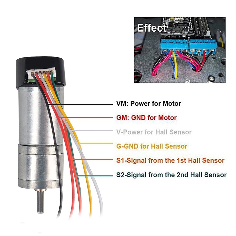
Wire Function Black Power for Motor Red Ground for Motor White Power for Hall Sensor Yellow Ground for Hall Sensor Orange Signal from 1st Hall Sensor Green Signal from 2nd Hall Sensor Captures
So What Were The Earlier Signals?
Onward and Upward!