Zigbee Lights Hack
Hacking a Zigbee Lightbulb
I have some smart lights installed in my house. They're great. You replace your regular light bulbs with Aduro Zigbee bulbs, put some Zigbee light switches over your existing ones, pair them all with your hub, and you're done.
You get native Zigbee grouping, which means your lights work offline, and you also get to control them from the Vivint app, which opens you up to all sorts of useful automations and such.
But the problem is the ecosystem I'm tied into doesn't support any in-wall Zigbee relays. So if you're trying to smartify a multigang lightswitch that also controls, say, ceiling fans or fluorescent bulbs, you're kind of out of luck. My ecosystem provides passthrough plates for their lightswitches, so you can still smartify some of the gangs and expose the physical switch on other gangs, so this wasn't a problem for a while. But I want my whole house smartified, darn it!
You can find Zigbee relays online for pretty cheap, but my ecosystem doesn't currently support Zigbee devices from outside its ecosystem. So what to do?
My solution was pretty clever, I thought. I would take the guts out of a supported Zigbee bulb, reverse engineer whatever signal the microcontroller was outputting to the LED control circuitry, and use that to turn a relay on/off.
Taking apart the bulb, I found that there was a PWM signal that corresponded to brightness, and boom! I'm off to the races.
I threw together a low pass filter for that PWM output, connected it to a transistor, added a flyback diode and a relay, and I had a working prototype!
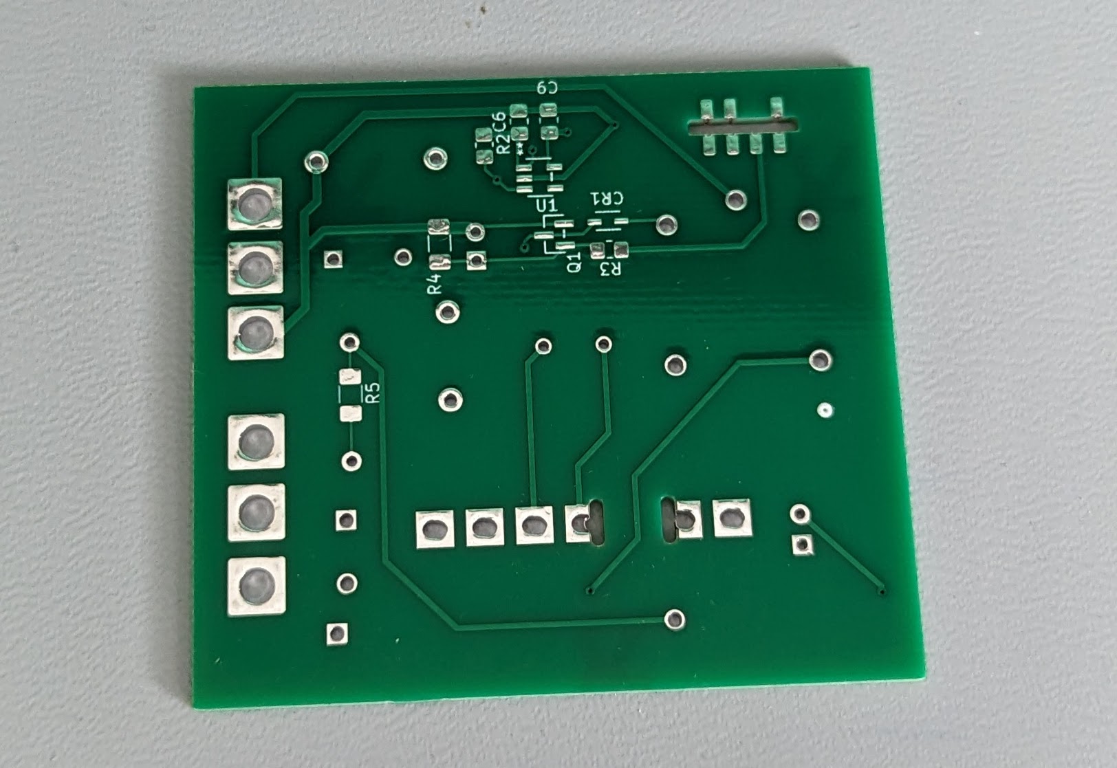
PCB Design
It took a little longer to design a PCB. Man, sourcing parts is just the least fun step of the whole process. Designing, testing, laying out the circuit? A blast. Finding parts and double checking their specs will line up with your design? Such a drag.
I found a nifty little module to give me 5V DC from mains power, the LS03-13B05R3. It was pretty cheap and even though the support caps took a fair bit of space and BOM cost, it's way smaller than my previous attempt at doing AC -> DC conversion.
After a few weeks, I had some cheap PCBs and was ready to start soldering!

PCB Assembly
This was not my first time soldering SMT devices, but it was my first time soldering anthing smaller than a 1206. My old technique of using the iron the whole time and tacking down one end and then the other is just inadequate. You need to use tweezers and a hot air reflow for smaller components. There are presumably still some 0805 pieces in my office carpet that will remain til the end of time.
And here's the finished piece:

Time to test it out!
Here's my first mistake. I didn't do any sort of continuity sanity check when I first got the PCB. If I had, I might have realized that I had a pad reversed on the Zigbee daughterboard. Thankfully, it was a non-connected pad, but my goodness, what a terror!